

Sinclair C5 - Simplified Relay Controls
This set of instructions show how to re-wire a C5 with the original 12V motor if you either have no installed electronics, or your original electronics have been damaged when the battery has been connected with the wrong polarity.
It also shows how to connect up a 12v supply to the original control box which will still supply the original lights, indicators and horn. And shows the basics of putting in an ammeter/voltmeter to monitor the system on the move.
A fully functional circuit for a 24V system is also included that shows how to wire in a Porter 10 Speed controller - more for the more advanced user.
Twin Relay Solution 12V - No Accessories
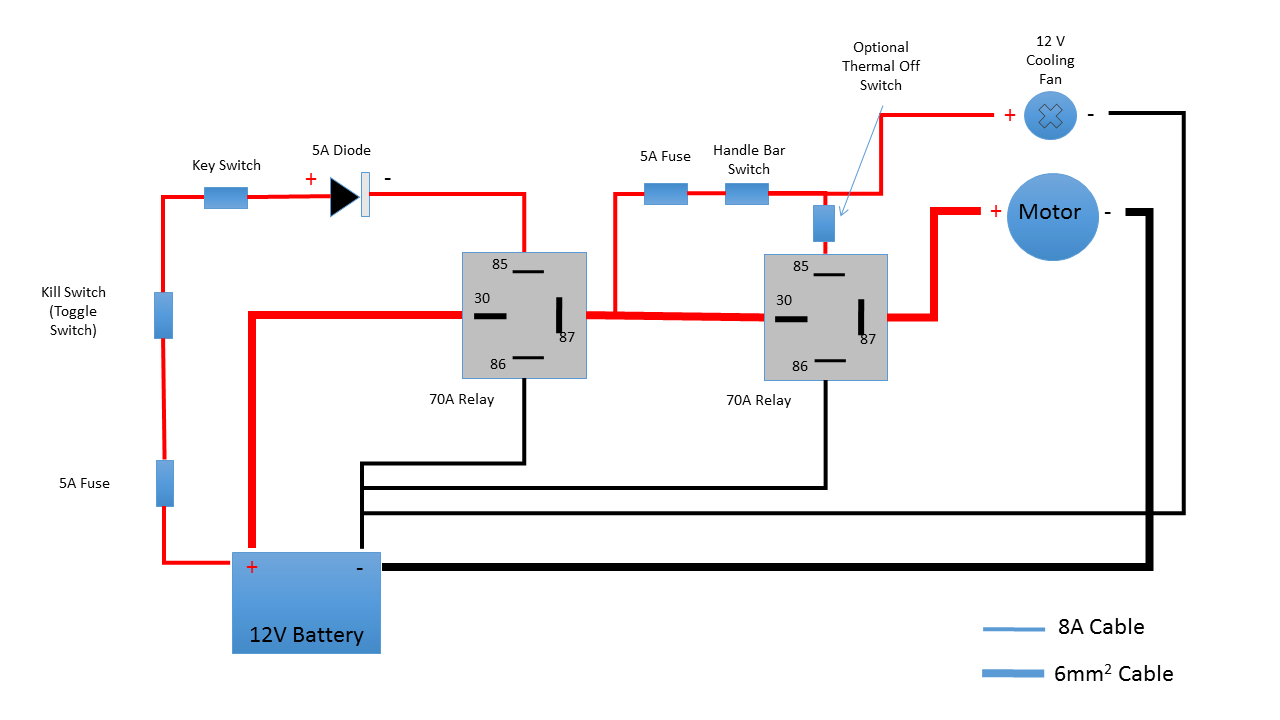
Notes
This Circuit will get your motor running if you have fried the pod or have a C5 which has none of the original electronics left on the chassis.
6mm2 cable is quite expensive, and is but can be bought short lengths from eBay. A good alternative to it is to use a set of cheap 100A Jump leads. These are the ones rated for petrol cars up to 1.4 Liter, and can be bought in budget shops or on eBay for less than the cost of the 70 A Cables. (It is of course possible to use the original wiring cables. Brown = Red, Blue = Black in the diagram above).
To ensure the Diode is fitted correctly, the Silver band on the relay should be on the side of the wiring closest to pin 85. The diode will stop the motor running backwards.
The pin numbers on the relay are the same as the ones on the bottom of the actual ones. On any 4 Pin Relay Pins 30 and 87 are the load pins, and are connected when the electromagnet is energized by making the making the circuit across pins 85 and 86.
The Kill switch can be fitted in line with the Handle Bar switch after the 5A fuse on the 8A cable between Pin 87 on the first Relay and Pin 85 on the second relay.
The Thermal Switch is the one that is fitted to the motor with the orange cables coming out of it. On the original circuit it's the secondary thermal protection for the motor, on this one it's the only one. However the cooling fan should help mitigate the need for one.
The Cooling Fan is simply an 80 mm computer cooling fan. On the circuit above it runs when the motor is on, If you want to have it running all the time wire it directly back to Pin 87 in the first relay, so it will stay on when the first relay is energized.
In the next diagram we'll look at how to get an indication of Battery Voltage and how to resurrect the lights, Indicators and horn if you have them fitted.
Parts List: 12 V System
- Automatic Wire Stripper/Crimping Tool
- 6mm2 cable 2m Red, 2m Black (A cheaper alternative is a set of cheap 100A jump leads)
- 1 Set of Quick release Battery terminal connectors. ( Make it easier to remove the battery for charging).
- 8 Amp Cable, 1 reel Red, 1 Reel black, 5 or 10m reels will suit.
- 2 Off Automotive Fuse Holders, 2 5A fuses to suit holders
- One 2 Pin Toggle Switch, One 2 Pin Key Switch ( Optional).
- 1 off 5Amp rated 100V Diode
- 1 Off Strip 5A Connector Block ( to connect the diode and computer fan).
- 2- off 70 Amp 12V Automotive Relays
- 1-Off 80 mm 12Volt 2 Wire Computer Fan.
- Pack of 10 Yellow 35 Amp 9.5mm Spade Connectors ( Fit the big pins on the Relays, and the motor Terminals, Go for the non insulated type)
- Pack 10 Yellow 35 Amp 8mm Ring Connectors ( Optional if you don want to disconnect the original motor cables)
- Pack of 20 Blue 15Amp 6.3mm Female Spade connectors ( For the Small relay terminals and Switches)
- Pack of 10 Blue 15Amp 6.3mm Male Spade connectors (For connecting cables inline with fuses)
- Roll of Insulating Tape - to cover the the connector block and to add strength to the crimped joints
Notes
It's advisable to have one of the Automatic Wire Stripper/Crimping Tools in your toolkit for this work. It will cut all the cables and will also strip the wires and crimp the connectors to the cables.
If you don't have one do a search on eBay and you can pick them up for somewhere in the region of £5 - £15.
Twin Relay Solution - How to Power Lights and indicators
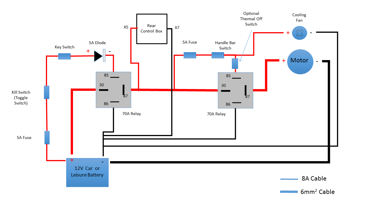
Notes
If your C5 had a pod and rear control box you can still power the rear control box by running 8A cables to the terminals numbered above. These are just inside the inspection cover at the top of the control box.
This will still allow the Lights, Indicators and horn to be powered up using the original Sinclair instructions that can be found in the Resources section. The control box is fully fused, so no need to add any.
The following Diagram shows how to add a Combined Voltmeter and Ammeter to give an indication of Battery State and load on the motor to give similar indications to the original pod.
Twin Relay Solution - Including Shunt for Current & Voltage Monitoring
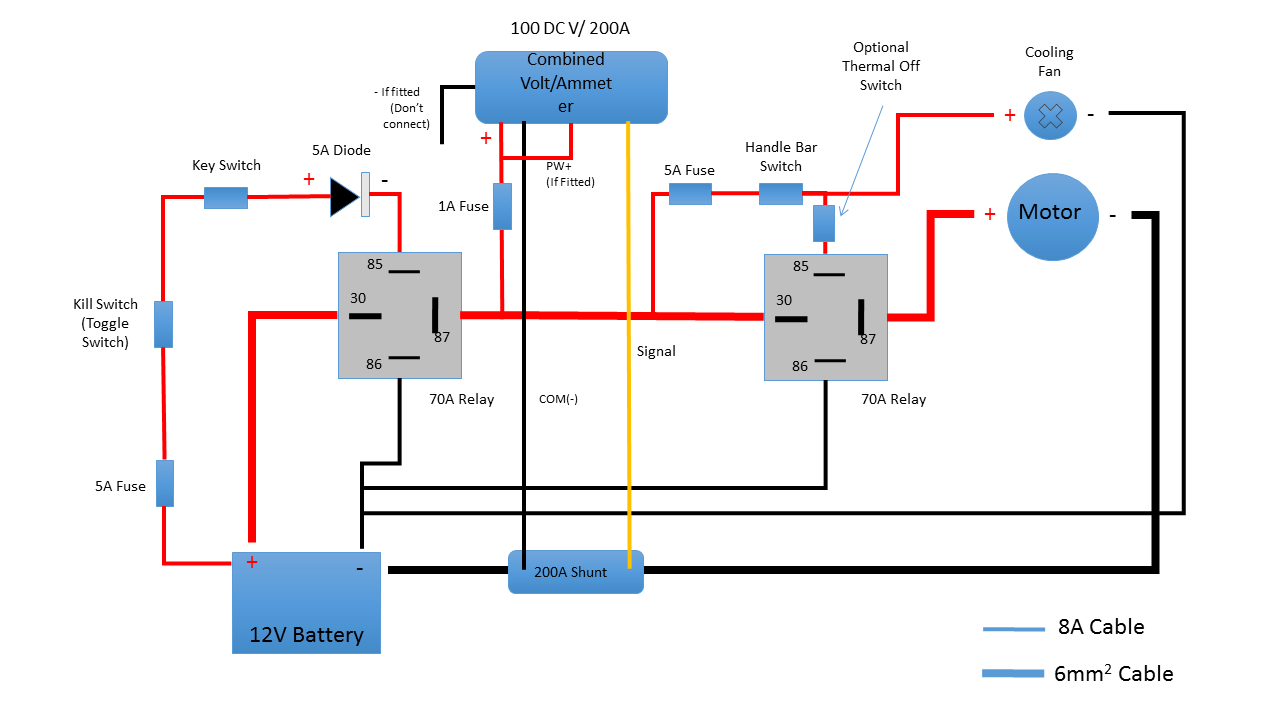
Notes
This shows a 5 wire Combined meter. It can be fitted up front in a modified Pod housing. A 3 Wire one is available, and will be slightly easier to connect up.
To wire it up you will need to run cables up the inside of the tunnel. Make sure your cables are cable tied to the steel chassis and don't foul the chain or pedals. Use a connector block to connect up the heavier cables to the thin signal wire. The connection to the shunt is with yellow 30Amp round connectors.
When the motor is running at it's normal load on the flat it will give a current of 29-30 Amps, when it goes above 30 Amps you really need to start pedaling! 40 amps is quite normal climbing a hill as you assist whilst pedaling. When it drops below 5 Amps the motor isn't doing much, so switch off and coast.
Voltage - A fully charged battery will be Somewhere between 13.5 - 14.4Volts. (There's not much charge stored above 13.5 Volts) However to avoid damaging the battery Stop when the voltage drops to 10.5 volts. It will start to do this when you are running, but the voltage on a lead acid battery will recover if you stop for a minute or two. Once it goes back up to about 11.5 volts you will be good to go for a further mile or two - head home and recharge.
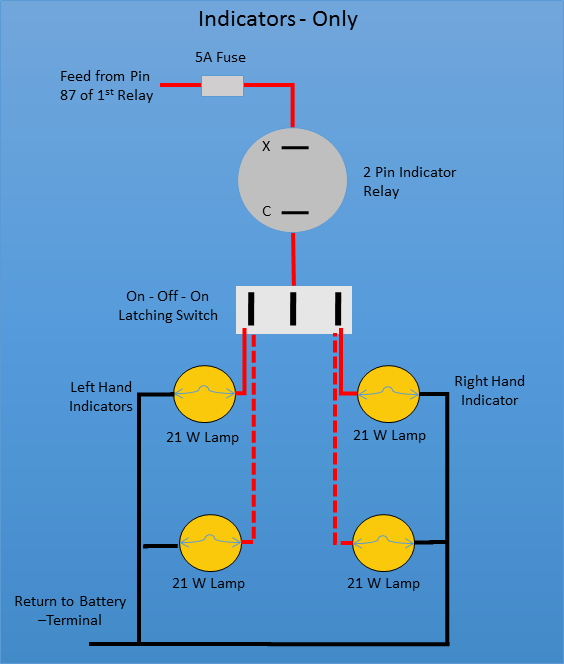
If using LEDs instead of conventional lamps, you need to change the Indicator relay to an LED compatible one, and drop the fuse size to 2A.
The LED lamps will need to be wired round the right way or they may not illuminate. If they are wrong just swap the polarity of the wires.
Notes
Indicators.
You'll only need to build this from scratch if you have no Control box. The diagram shows how to wire up using an On - Off - On switch with a 2 pin Indicator relay.
The switch will need mounted on a bracket, or you can go mad and buy a motorcycle style switch that allows you to operate the indicators from the handlebar. ( Pretty cheap on eBay). Motorcycle switches also have the horn switch attached too, so it could be used to replace the original horn switch. 8 Amp cable will work well in this application.
The next diagram shows how to wire in a Hazard warning system.
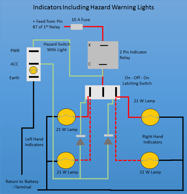
If using LEDs instead of conventional lamps, you need to change the Indicator relay to an LED compatible one, and drop the fuse size to 5A.
Units with Buzzers are best as you can hear it's still on, and means you don't need an extra signal Wire for an enunciator lamp off the 3rd Pin of the 3 pin type.
The LED lamps will need to be wired round the right way or they may not illuminate. If they are wrong just swap the polarity of the wires.
The Diodes are 5A diodes.
You can use a simple 2 Pin switch for this, but 3 pin hazard switches are available that would suit this. Only the hazard switch with a lamp in it will need the connection to the negative connection of the battery.
8 Amp Cable will suit the whole build.
Notes
For this you'll need, a Hazard warning switch, you can use a 2 pin switch if you don't want a flashing light on the switch. The 5A diodes stop the circuit lighting up the right and left hand indicators when the circuit is being used normally.
If using an LED Circuit make sure your hazard switch has an LED as well, or your circuit may pulse rather than flash, or may not flash at all!
Using normal lamps and indicator relay it won't matter what type of lamp in is in the switch.
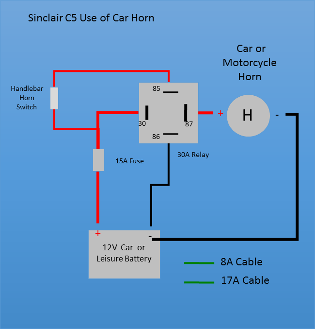
If you want a Loud horn you can fit a car or motorcycle horn.
Typical car horns need 120Watts of power to drive them. So these will draw a current around 10 Amps. To run one therefore needs a relay fitted to cope with the power. ( Don't press it going up hill, or you'll slow down!)
A 30 Amp relay is suitable for this job. Some 30A relays are fitted with a fuse, a 15A one can be used. If the relay you choose has no fuse fit an inline one that can accept a 15A fuse.
I used a 1.5 Amp motorcycle horn which is loud enough, and makes enough noise to be heard, and the public are more tuned to hearing such a noise than the original buzzer. A 5A fuse will be fine for that in place of the 15A one for a car horn.
Notes
The original circuit on the control box was designed to run a small buzzer, so if you want to drive a car or motorcycle horn, then you'd be best to use this circuit.
Twin Relay Solution 24V - Including Shunt for Current & Voltage Monitoring
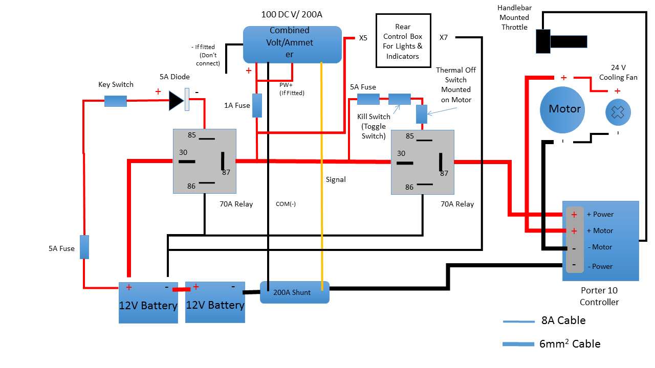
Notes
This shows a 5 wire Combined meter. It can be fitted up front in a modified Pod housing. A 3 Wire one is available, and will be slightly easier to connect up.
To wire it up you will need to run cables up the inside of the tunnel. Make sure your cables are cable tied to the steel chassis and don't foul the chain or pedals. Use a connector block to connect up the heavier cables to the thin signal wire. The connection to the shunt is with yellow 30Amp round connectors.
Special thanks to John Wilson for putting together the above information.