All I need is a wiring diagram?
Yeah, I haven't done a wiring diagram

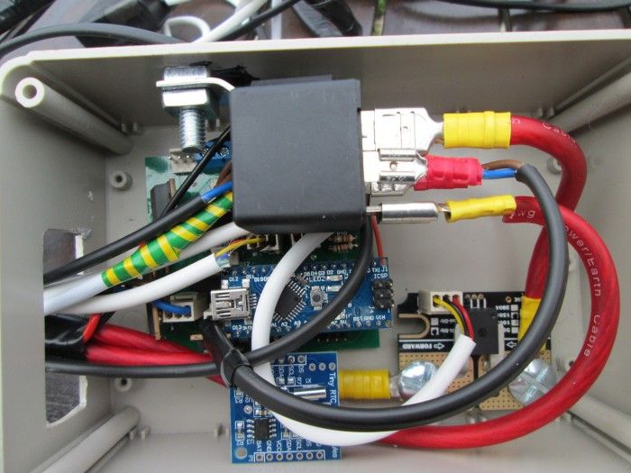
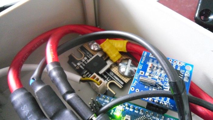
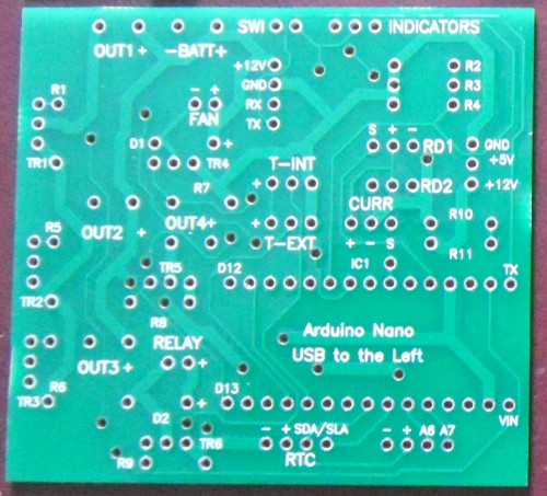
Instead use the pcb layout and this key to workout what plugs into where:
OUT1 = LEFT INDICATOR (Follow polarity markings on the pcb)
OUT2 = RIGHT INDICATOR
OUT3 = FRONT/BACK LIGHTS
OUT4 = EXT LIGHTS
RELAY = Relay!
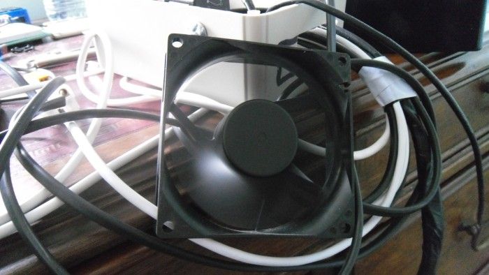
FAN = Cooling fan
SWI = handlebar switch
INDICATORS = Indicator left, common, right
T-EXT = LM35 that needs to be strapped to your C5 motor, same pinout at T-INT
RD1 = Reed switch, follow pcb markings
CURR = Current module, follow pcb markings
what wire to get ?
I had a load of 3A rated wire hanging around so I used mostly that plus the handlebar switch/indicators are all the original cabling.
I'll take the first project. box you had if you don't mind to use as a template

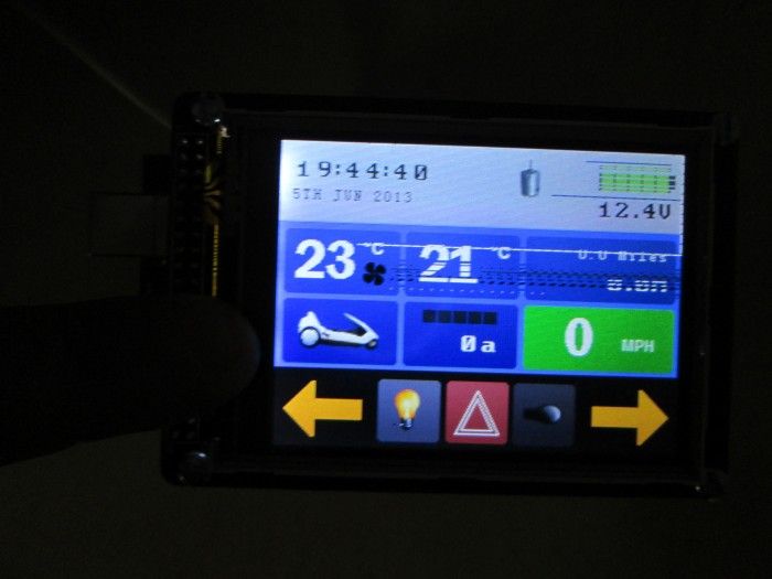
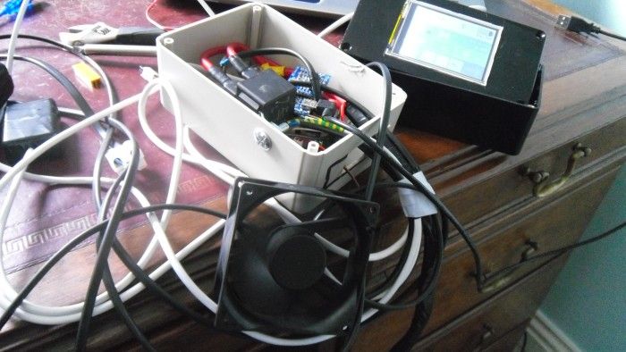
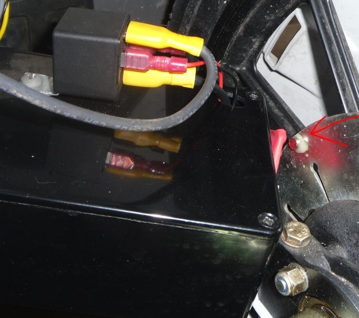
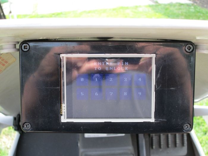
That box you see in the picture is my first (and only) project box which needs to remain on the C5. Its got loads of extra holes in it[woot].
I still haven't worked out where I'm going to put the relay. Inside the box theres not much room, and on top of it is where its going to stay for now.
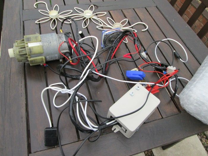
2 frames and an axle what other bits you got ?
2 other C5s and not much else. A bunch of original (worn-out) tyres from the C5s. Oh, and a Zike & Indicators that's currently on Ebay.
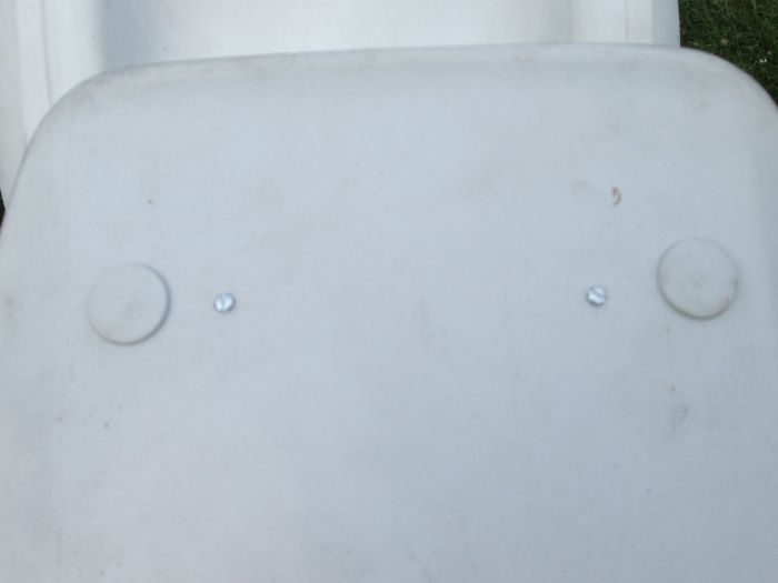
Noticed you have no top hats at rear end got a spare 1 if you want it ?
Yeah they'd be useful, how much? I do have 1 set to go between 3 C5's but I don't usually have them on the C5 when I go out as they just come loose and vanish

if I'm not careful.
posted on: 05/06/2013 21:02:50


 :
:


 )?
)?